
The ‘pingometer’ gives a visual indication of how much lag there is between your Raspberry Pi and your desired server on the internet. As the Raspberry Pi will be connected to the same network as your PC or games console, this will give you an indication of just how much delay there is between your network and the online game server that you want to play on. It does this using a Linux network command called ‘ping’ that tells you how long it took for a small packet of data to get to the server and then back to your computer. This value is in milliseconds (thousandths of a second).
The full article can be found in The MagPi 39
As well as a servo-controlled meter indicating the ping time (between 0 and 1,000 milliseconds), an RGB LED will change from green for a fast ping, to orange for an okay ping, to red for a slow ping. If the ping fails to connect to the remote server, then the LED will be blue.
You'll need...
9g mini servo motor
Raspberry Squid RGB LED
3× male-to-female jumper wires
Cocktail stick (to make needle)
Glue
Small food container as an enclosure
Drill and craft knife
As you’ll see from the list of required components on the previous page, this project has both the servo motor and RGB LED module plugged directly into the Raspberry Pi GPIO pins, so no breadboard is needed.
The servo motor is of a type called 9g, and you can find these on eBay for very little money.
The RGB LED is a device called a Raspberry Squid that combines a bright 10mm RGB LED with built-in current-limiting resistors and female header leads. You can find full instructions for building your own Squid on the GitHub page for the Squid’s accompanying library. If you would rather buy a ready-made Raspberry Squid, however, you can find one on Amazon or look on the Monk Makes website for more info.
The food container came from a supermarket and has the nice feature that if you leave the top clip undone, it acts as a diffuser for the LED.
Servo motors
The key to this project is the servo motor that moves the meter needle. Servo motors are different from more conventional motors in that they are not free to rotate continuously. In fact, they can only normally rotate about 180 degrees.
Servo motors have three leads: two power leads (ground and 5V) and a control lead. The control lead is fed a series of pulses of varying length. The length of the pulses will determine the servo motor’s angle. If the pulses are around 1 millisecond, the arm of the servo will be at one end of its range - let’s call that 0 degrees. A pulse length of 1.5 milliseconds will position the servo arm right in the middle of its range (90 degrees), and a 2 milliseconds pulse will put the arm at the far end of its range (180 degrees). In practice, servos often don’t do the full 180 degrees – the range is sometimes more like 0 to 170 degrees.
Building your project
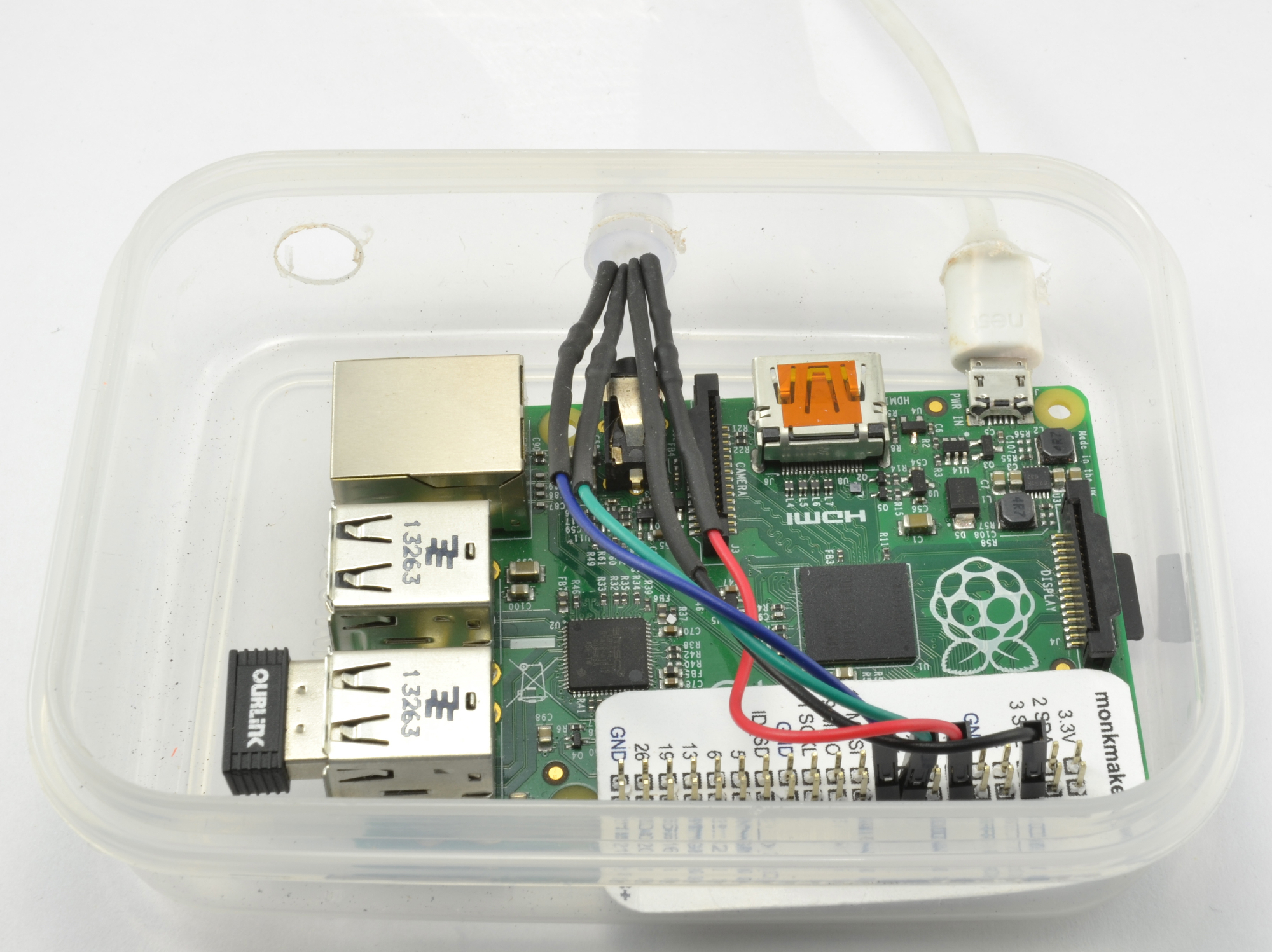
This is a pretty straightforward project to build. Everything just plugs into the GPIO header pins. Connect the black header of the Raspberry Squid to a GND connection of the GPIO header, the red lead to GPIO 18, the green to GPIO 23, and the blue to GPIO 24.
When you first plug the servo onto the GPIO connector, there will be a surge of current, and this can be enough to cause your Raspberry Pi to reset. So it’s best to attach the servo to your Raspberry Pi while it is powered off.

Use the three female-to-male jumper wires to connect the brown lead of the servo to a GND pin on the GPIO connector, the red servo lead to 5V, and the orange lead to GPIO pin 25.
Fit one of the servo arms loosely onto the motor, just so that you can see the servo moving, and jump ahead for a moment to the software section to try out the project before you go boxing everything up
Use a hot glue gun, or other glue, and stick the cocktail stick onto the servo arm. You may need to shorten the stick a little to suit the size of your container. Carefully cut out a rectangle in the lid for the front of the servo to push through, and glue the servo in place. Resist the temptation to screw the servo arm firmly into place just yet, as some adjustment will probably be necessary later.
Drill 10mm holes in the box for access to the USB socket and for the Raspberry Squid. If you are using an Ethernet connection, then you will need another hole for that. We used a USB WiFi adaptor. Make sure that everything lines up okay for the servo motor.
In the code downloads for this project you will also find an image file for a very simple scale. You can print this out, cut it down to size, and then stick it on the inside of the plastic food container.
Building your pingometer
As with all projects, it is a good idea to test the project out and get everything working while the parts are all out on your workspace. Once you know all is well, you can install the project in its enclosure.
Now that the hardware side of the project is complete, we just need to get the software running. The program is written in Python and uses the Squid library to control the colour of the Raspberry Squid. To install the Squid library, make sure that your Raspberry Pi has an internet connection and then run the commands:
git clone https://github.com/simonmonk/squid.git
cd squid
sudo python setup.py install
You can download the program for this project from your Raspberry Pi command line, using:
git clone https://github.com/simonmonk/pi_magazine.git
To run the program, change directory to the one where the code for this project lives and then run the program using the commands below:
cd /home/pi/pi_magazine/09_pingometer
sudo python pingometer.py
When you run the program, you may find that the needle is in the wrong place. The section on using
the pingometer will explain how to fix this.
How the code works
The Python code for this program is pretty heavily commented. You will probably find it handy to have the code up in an editor while we go through it.
The program starts by importing the subprocess, time, RPi.GPIO and squid libraries that it needs.
The constant HOSTNAME is used to specify the server whose ping is to be measured. If you are using this project for gaming, then put the address of the gaming server that you are going to use here.
The PINGPERIOD variable determines how often the ping is measured, and GOODPING and OKPING determine the colour that the Squid will display. If the ping is less than GOODPING, the LED will be green; if it’s greater than GOODPING but less than OKPING, it will be orange; otherwise it will be red.
The variable SERVOPIN specifies the pin used to control the servo motor, and MINANGLE and MAXANGLE determine the servo arm’s range of movement, as we don’t want it swinging through its full 180 degrees.
Next, the SERVOPIN is set up as a PWM pin so that we can generate pulses of the right length to move the servo.
The variable squid is initialised using the GPIO pins for the red, green, and blue channels (18, 23, and 24).
The function mappingtoangle converts a ping time of between 0 and 1 seconds to an angle between MINANGLE and MAX_ANGLE.
The function setangle sets the servo pulse to the correct duty cycle, and so also sets the pulse length to position the servo. To prevent excessive jittering, after generating pulses for 0.2 of a second, the duty is set to 0. This has the effect of the servo arm moving to the correct position and then staying still until setangle is called again.
The code to actually get the ‘ping’ is contained in the ping function. This makes a Linux system call to ping, capturing what would normally appear in the terminal into the variable output. This would look something like:
round-trip min/avg/max/stddev = 23.739/23.739/23.739/0.000 ms
The ping command uses the -c 1 parameter, so only one ping is made and the minimum, average and maximum are all the same value. To extract that value (23.739 in the example above), the string is split into an array of strings separated by ‘/’. The content of index 5 of this array will be one of the elements containing this number. Dividing it by 1,000 changes the units from milliseconds to seconds, as used in the rest of the program. If the call to ping fails for any reason, then the try/catch structure will ensure that the function returns -1.
The main loop repeatedly measures the ping and then sets the servo position and LED colour accordingly.
Using your pingometer
Below the line p = ping(HOSTNAME), there is alternative code for setting p, simply by inputting a value. To make it easier to position the servo arm, remove the # from the front of this line and run the program again. Enter a value of 0.5 for p and after the arm has moved, remove the arm from the servo and then put it back, but pointing straight up, as this is the central position for the meter. You can then put the # back in front of the line again when you are done.
The settings used here for GOODPING and OKPING are correct for your expert’s somewhat slow network where he lives. You will probably need to change these values to suit your setup.
Code listing
import subprocess, time
import RPi.GPIO as GPIO
from squid import *

HOSTNAME = "us.mineplex.com"
# HOSTNAME = "google.com"
PING_PERIOD = 3.0 # seconds
GOOD_PING = 0.1   # seconds
OK_PING = 0.3     # seconds

SERVO_PIN = 25 # control pin of servo
MIN_ANGLE = 30
MAX_ANGLE = 150

# Configure the GPIO pin
GPIO.setmode(GPIO.BCM)
GPIO.setup(SERVO_PIN, GPIO.OUT)
pwm = GPIO.PWM(SERVO_PIN, 100) # start PWM at 100 Hz
pwm.start(0)

squid = Squid(18, 23, 24)

def map_ping_to_angle(ping_time):
    # ping timeout of 1000 ms sets maximum
    # ping min of 0
    # Fast ping needle over to the right
    angle = ping_time * (MAX_ANGLE - MIN_ANGLE) + MIN_ANGLE
    if angle > MAX_ANGLE :
        angle = MAX_ANGLE
    if angle < MIN_ANGLE :
        angle = MIN_ANGLE
    return angle

# Set the servo to the angle specified
def set_angle(angle):
    duty = float(angle) / 10.0 + 2.5
    pwm.ChangeDutyCycle(duty)
    time.sleep(0.2); # give the arm time to move
    pwm.ChangeDutyCycle(0) # stop servo jitter

def ping(hostname):
    try:
        output = subprocess.check_output(
"ping -c 1 -W 1 " + hostname, shell=True)
        return float(output.split('/')[5]) / 1000.0
    except:
        return -1

try:
    while True:
        p = ping(HOSTNAME)
        # p = input("ping=")  # Use for testing
        print(p)
        set_angle(map_ping_to_angle(p))
        if p == -1 :
                squid.set_color(BLUE)
        elif p < GOOD_PING:
                squid.set_color(GREEN)
        elif p < OK_PING:
                squid.set_color((50, 15, 0)) # Orange
        else:
                squid.set_color(RED)
             time.sleep(PING_PERIOD)
finally:
    GPIO.cleanup()


