01. LCD character display
This project is based around an LCD display. Our display has 16 characters across two lines and is often referenced as a ‘1602’. These usually contain an HD44780, or equivalent, driver chip that displays the appropriate pixels that make up the characters.
One downside of the display is that the driver chip needs at least six data connections. This uses up GPIO ports, as well as needing lots of wires to the LCD display. A common solution is to have a ‘backpack’ fitted to the rear of the LCD display using a port expander. The example used here is a PCF8574T 8-bit port expander.
02. Designed for 5 V
The port expanders are available on a PCB backpack pre-soldered onto the back of the LCD PCB. This saves you from having to create your own circuit, but it does come with an issue. These circuits are normally designed for 5 V, whereas a Pico uses 3.3 V for the GPIO ports.
Connecting a 5 V signal to a Pico GPIO port could cause permanent damage to the latter, so this tutorial looks at some of the possible solutions to interfacing between devices designed for different voltages.
03. Move pull-up to 3.3 V
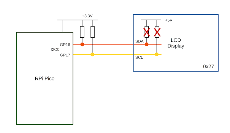
If the 5 V device did not have a pull-up resistor, the I2C bus could work with pull-ups to the 3.3 V supply instead. This is shown in Figure 2. The crossed-out resistors are the pull-ups inside the LCD I2C backpack and the two pull-up resistors on the left are connected to the 3.3 V output on a Pico. Unfortunately, this involves de-soldering surface-mount devices, which can be difficult.
04. Unidirectional level shifter
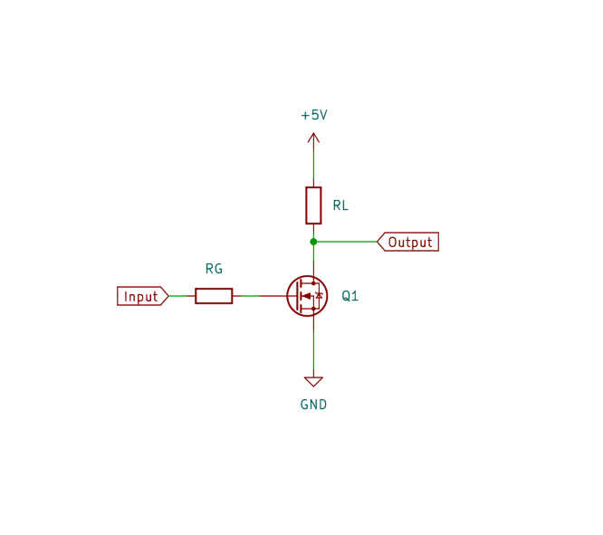
A simple form of level shifter can be used when controlling 5 V devices from a 3.3 V microcontroller or computer. This is often used for controlling NeoPixels from a Pico or a Raspberry Pi. In its simplest form, this is a MOSFET with two resistors (as shown in Figure 3). The gate resistor RG (typically 470 Ω) reduces the in-rush current, and RL is a pull-up resistor (typically 2.2 kΩ to 10k Ω). With no input, the pull-up resistor sets the output high. When a 3.3 V input is provided, the MOSFET turns on pulling the output low. This results in an inverted signal.
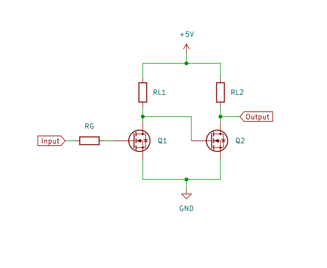
The code can be configured to invert the output, or you could add an additional MOSFET to invert it a second time. A two-stage, non-inverting buffer is shown in Figure 4.
05. Bidirectional level shifter
The LCD is controlled from your Pico, so you may expect the signal would only need to go in one direction. However, due to the use of I2C protocol, signals need to pass in both directions. We need a bidirectional level shifter. These can be made using individual MOSFETS, but using a premade level shifter from Adafruit or SparkFun is more convenient. An example is the Adafruit bidirectional level shifter, which has four level shifters on a convenient PCB. This is shown in Figure 5.
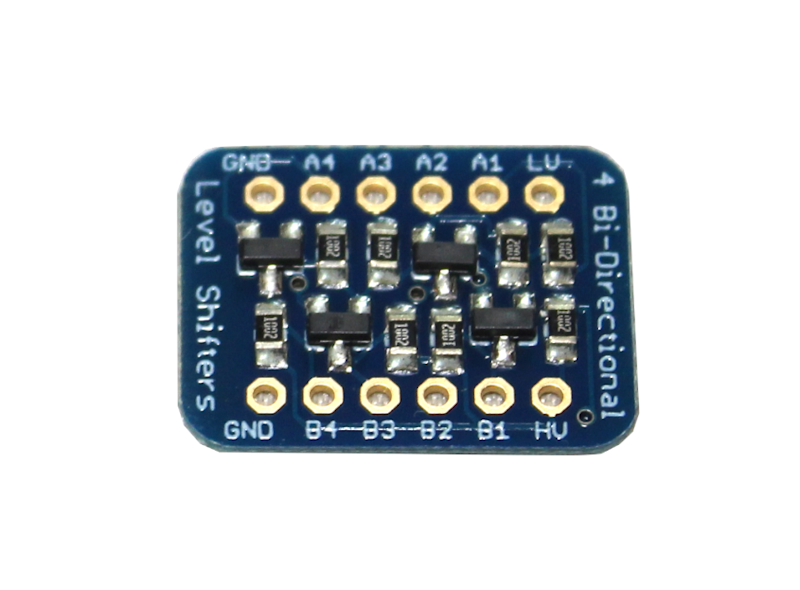
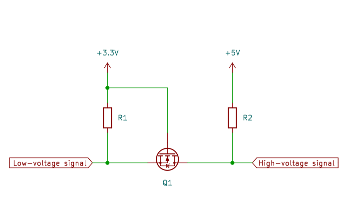
The level shifter has just one MOSFET for each channel. This is in an unusual configuration. The circuit can be thought of as two sides, with the left side being for the low voltage and the right for the higher voltage. The MOSFET joins the two together. The schematic diagram is shown in Figure 6.
06. How the level shifter works
If both the low-voltage and high-voltage signals are high, then the MOSFET is off and the signal is high at both sides. If the low-voltage signal (left) drops low, then the MOSFET is in the forward direction and the voltage at the gate will turn the MOSFET on. This will provide a path to ground and so the high-voltage signal (right) will be pulled low. If the high-voltage signal (right) goes low, due to an internal characteristic of the MOSFET a small current is able to flow in the reverse direction. As this happens, the voltage of the source pin dips, causing the MOSFET to turn on. This pulls the voltage down on the low-voltage signal as well.
07. LCD circuit
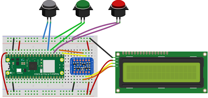
The level shifter can be inserted onto the breadboard and connected between your Pico and LCD display. Then it’s just a case of adding three buttons for Start, True, and False. These are shown in Figure 1.
The top power rail is used for 3.3 V taken from your Pico’s 3.3 V output, and the bottom power rail is 5 V taken from the VBUS supply from the USB port.
The buttons used are 16 mm push-to-make switches, similar to arcade buttons, but smaller. You can use other push-to-make switches if you prefer.
08. Download the LCD library
The libraries that support the LCD display with backpack are available from GitHub. Upload the files lcd_api.py and pico_i2c_lcd.py to your Pico. You can see a demo using pico_i2c_lcd_test.py. This can be useful for checking your wiring is correct, but you will need to change the pins used for SDA (GPIO 16) and SCL (GPIO 17).
09. Coding the game
The game code (quizgame.py). starts by setting up the three
buttoni2clcdThen it enters a loop which ensures that the game can be played over again.
Within the first few lines of the loop, you can see that it first clears the display, puts a string which starts on the top line, moves to the start of the second line, and then puts another string to that line.
10. Handling button presses
The button presses are handled by having a
whiletrue_buttonfalse_button11. The quiz file
The questions are stored in the file quizfile.txt. This has one line per question. Each line should have three entries separated by a semicolon. The first entry is the top line to display, the second is the second line, and the final entry is a letter T or F to indicate whether the correct answer is
TrueFalseThe file is opened using the
withreadlinesTo separate the text to display from the answers, the
splitstripThe quiz file is created separately and must be uploaded to Pico.
12. Improving the game
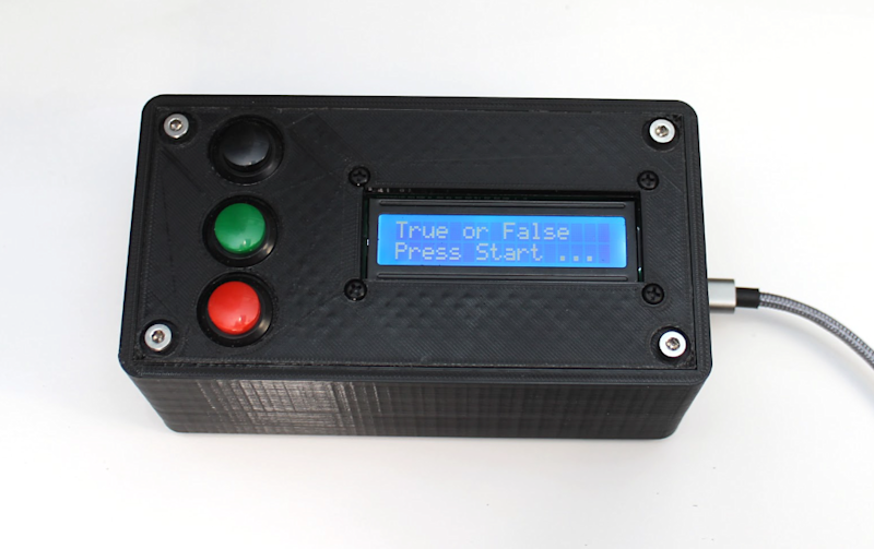
The game can be placed in an enclosure to make a complete game. You could start with a standard enclosure and cut holes for the display and buttons, or if you have a 3D printer you can download an example from the Penguin Tutor website. One improvement would be to add some error checking. Without error checking, if there is an invalid entry in the quiz file, the program may crash.
Another possible improvement would be to provide a way to add multiple quizzes rather than just limiting them to a single quiz.


